TolTEC Observation Planner and ECSV Upload
The ObsPlanner calculator can be used to plan observations and estimate sensitivity and integration times for the TolTEC camera on the 50-m LMT.
Receiver
TolTEC is a three-band imaging polarimeter that simultaneously observes at 1.1 mm, 1.4 mm, and 2.0 mm. The FWHM for its three diffraction limited beams are 5.0, 6.3, and 9.5 arcseconds, respectively. Each band has its own detector array of Lumped Element Kinetic Inductance Detectors (LEKIDs). Each TolTEC detector is sensitive to a single linear polarization of the incoming light, so each observation of TolTEC results in nine different images of the sky - one in each polarization of each of TolTEC’s three bands along with a total intensity map for each band.
Target Selection
The first step when using the TolTEC Obsplanner is to enter your source information and desired observation data and time into the box shown below:
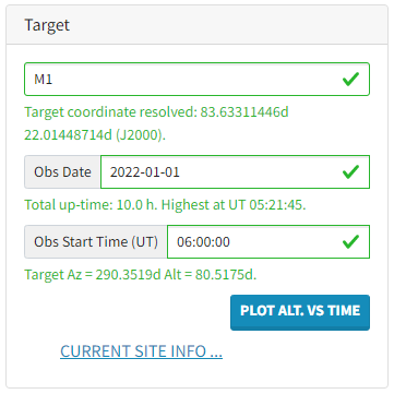
Targets can be searched by name in the first box or entered by RA and Dec. If entering targets by coordinates, users should make sure to use “hms” notation. Otherwise, the system will assume the coordinates are in degrees. Here is a video tutorial for this step in using the ObsPlanner.
Using the Obs Date and Obs Start Time (UT) boxes, users can explore when during the year their target is most available by plotting the altitude versus time for their desired date and time. The higher in elevation the target is, the better since the TolTEC sensitivity is dependent on the amount of atmosphere it has to look through.
Mapping Patterns
The TolTEC calculator allows users to choose between three different mapping patterns: 1) Raster pattern (for large maps), 2) Lissajous pattern (for small maps), and 3) Rastajous pattern (for intermediate maps). Each option comes up with a generic set of parameters for that map type, which users can choose to keep or adjust for their specific science target.
All three map types require input for the Desired RMS. The ObsPlanner will repeat the specified mapping pattern until this depth is reached, and the resulting time is shown in a final output table. This output table also gives estimates of the overhead time for the observation, map area, mapping speed, the on-target time per pass, and other values calculated for the observation.
Note: The ObsPlanner limits individual observation passes to a maximum duration of 60 minutes. This is for two reasons: 1) The drift in the telescope pointing should be checked each hour (roughly) with a pointing observation in order to limit astrometric errors. 2) The ObsPlanner is computationally expensive, and this is a shared resource. Proposers who wish to simulate the coverage of a set of observations lasting longer than 1 hour should split up their observation calculation and then manually coadd the resultant coverage maps.
Raster Pattern (video example):
The recommended map size for this pattern is greater than 30 arcmin on a side, which allows for a faster scan speed. In addition to overhead from pointing and other calibration options, the raster pattern has additional overhead from the fixed telescope turnaround period (typically about 5s) at the end of each row of the map.
| Input | Units | Description | Notes |
|---|---|---|---|
| Length | Deg. |
|
Shorter lengths and faster velocities lead to greater turnaround overheads |
| Space | arcmin | Step size between each row. | Recommend < array footprint |
| N Scans | Total number of rows in pattern. | NScans * Space + 4 arcmin gives the approximate map height | |
| Speed | arcmin/s | Scan speed across the pattern | Recommend > 50 arcmin/s * |
| Rotation | Deg. | Rotation angle with respect to the +lon direction | |
| Map Re ference Frame | Alt/Az or Ra/Dec. Alt/Az coordinates are recommended to optimize crosslinking for projects that have many map passes. | Galactic coordinates coming someday. |
*At this time, we do not know what the maximum usable scan speed of the telescope is, but we do plan to try to measure this in the fall of 2022.
Lissajous Pattern (video example):
The recommended map size for this pattern is on the order of 4 to 6 arcmin in diameter. Maps larger than this begin to develop a hole in coverage at the center of the map. The Lissajous pattern has 100% observing efficiency, so there is no additional overhead from the pattern itself.
We have also implemented a “Double Lissajous” pattern to allow Lissajous-style maps to be made on scales larger than 4 to 6 arcminutes diameter. We are still working on finding the best sets of parameters for this observing mode.
| Input | Units | Description | Notes |
|---|---|---|---|
| X Length | arcmin | Length in x direction | |
| Y Length | arcmin | Length in y direction | |
| X Omega | rad/s | Angular frequency in x direction | X_omega > 5 not recommended |
| Y Omega | rad/s | Angular frequency in y direction | Y_omega > 5 not recommended |
| Delta | Deg. | Phase angle between x and y directions | |
| Rotation | Deg. | Rotation angle with respect to the +lon direction | |
| T Exp | min | Exposure time of the observation | Calculator iterates until the desired depth is reached → may be > the input t exp |
Map Reference Frame |
Alt/Az or Ra/Dec. Alt/Az coordinates are recommended to optimize crosslinking for projects that have many map passes. | Galactic coordinates coming someday. |
Rastajous Pattern (video example):
The recommended map size for this pattern is anything between the Lissajous and Raster recommended map sizes (4 to 30 arcmin diameter). The Rastajous pattern has 100% observing efficiency, so there is no additional overhead from the pattern itself.
| Input | Units | Description | Notes |
|---|---|---|---|
| Raster Parameters | Length, space, n scans, speed | See raster pattern description | |
| T Turnaround | s | Time to turnaround on the edges of the map | Use space/speed to estimate |
| Rotation | Deg. | Rotation angle with respect to the +lon direction | |
| Delta | Deg. | Phase angle between the major pattern (raster) and minor pattern (Lissajous) | |
| Lissajous Parameters | X length 0, y length 0, x omega 0, y omega 0, delta 0 | See Lissajous pattern description | |
| Map Reference Frame | Alt/Az or Ra/Dec. Alt/Az coordinates are recommended to optimize crosslinking for projects that have many map passes. | Galactic coordinates coming someday. |
Atmosphere and Instrument Settings
Besides target selection and mapping parameters, there are two other major settings on the ObsPlaner (here is a video tutorial). The calculator includes three quartile atmosphere options: 25%, 50%, and 75%. The 25% atmosphere corresponds to the best observing conditions, where only 25% of nights at the LMT are better. The 50% quartile is the average atmosphere quality, where half of the nights at the LMT have better conditions, and the 75% quartile is the worst conditions, where 75% of nights have better conditions.
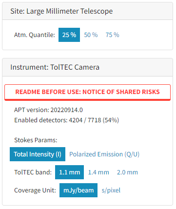
TolTEC’s polarization capabilities have not yet been tested but are expected to be explored during commissioning at the end of October after the Half-Wave Plate Rotator has been installed. This observing mode is still planned to be offered during the upcoming 2023-S1 cycle, and the ObsPlanner allows users to select if they want Total Intensity or Polarized Emission measurements.
Important Polarization Notes: 1) Every polarization observation also needs a corresponding total intensity observation, and 2) Polarimetry measurements must use a raster pattern in equatorial coordinates.
Uploading ECSV Results to Hedwig
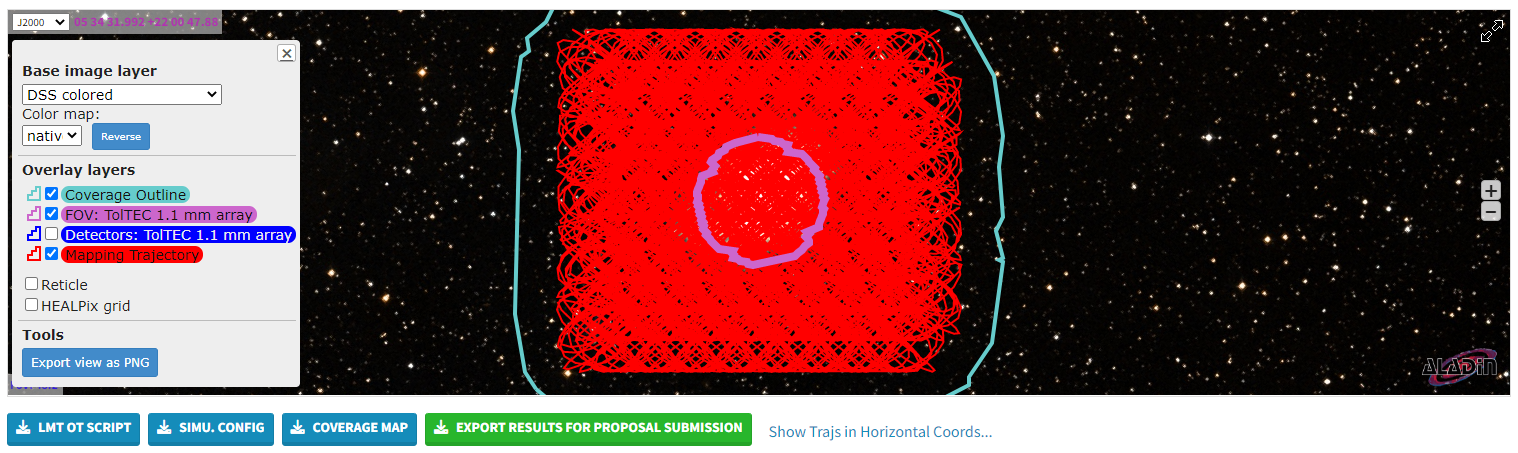
The results from the ObsPlanner can be exported as an ECSV file for submission during the proposal process. This file contains all of the inputs the user entered into the ObsPlanner and the results from the ObsPlanner. The Technical Review panel will use this file to assess the technical feasibility of the proposed project.
On Hedwig, proposals using TolTEC will be directed to the page shown below:
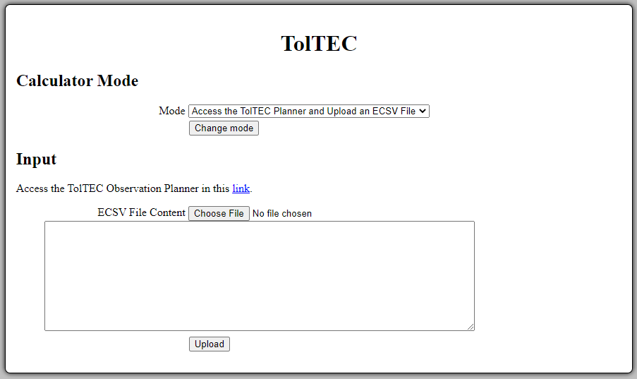
The downloaded ECSV file from the ObsPlanner is then uploaded into Hedwig for submission. The contents of the file will be automatically populated into the text box below the choose file button. Please keep in mind that whitespace matters in ECSV files, so the contents of the file should not be edited from what the ObsPlanner produces.